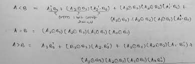
N BIT PARALLEL ADDER
Parallel adder is a binary adder circuit implemented to add two binary number having N-bits (for example, to add 4-bit binary numbers, we use 4- bit parallel adder, and so on).
As its name implies, the parallel adder is a digital combinational circuit that adds two binary numbers in parallel form and generates the arithmetic sum of those binary numbers in parallel form.
We can implement an N-bit parallel adder with the help of full-adders connected in a chain fashion.
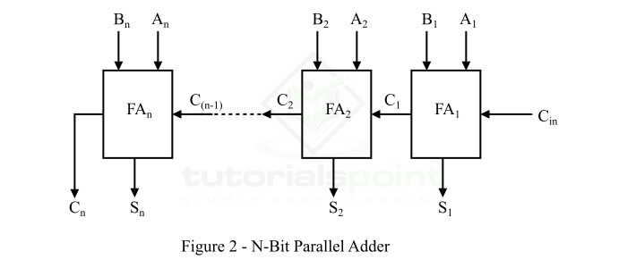
N BIT PARALLEL SUBTRACTOR
A Parallel Subtractor is a digital circuit capable of finding the arithmetic difference of two binary numbers that is greater than one bit in length by operating on corresponding pairs of bits in parallel.
The parallel subtractor can be designed in several ways including combination of half and full subtractors, all full subtractors or all full adders with subtrahend complement input.
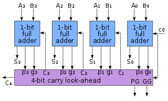
CARRY LOOK AHEAD ADDER
A carry-lookahead adder (CLA) or fast adder is a type of electronics adder used in digital logic. A carry-lookahead adder improves speed by reducing the amount of time required to determine carry bits.
It can be contrasted with the simpler, but usually slower, ripple-carry adder (RCA), for which the carry bit is calculated alongside the sum bit, and each stage must wait until the previous carry bit has been calculated to begin calculating its own sum bit and carry bit.
The carry-lookahead adder calculates one or more carry bits before the sum, which reduces the wait time to calculate the result of the larger-value bits of the adder.

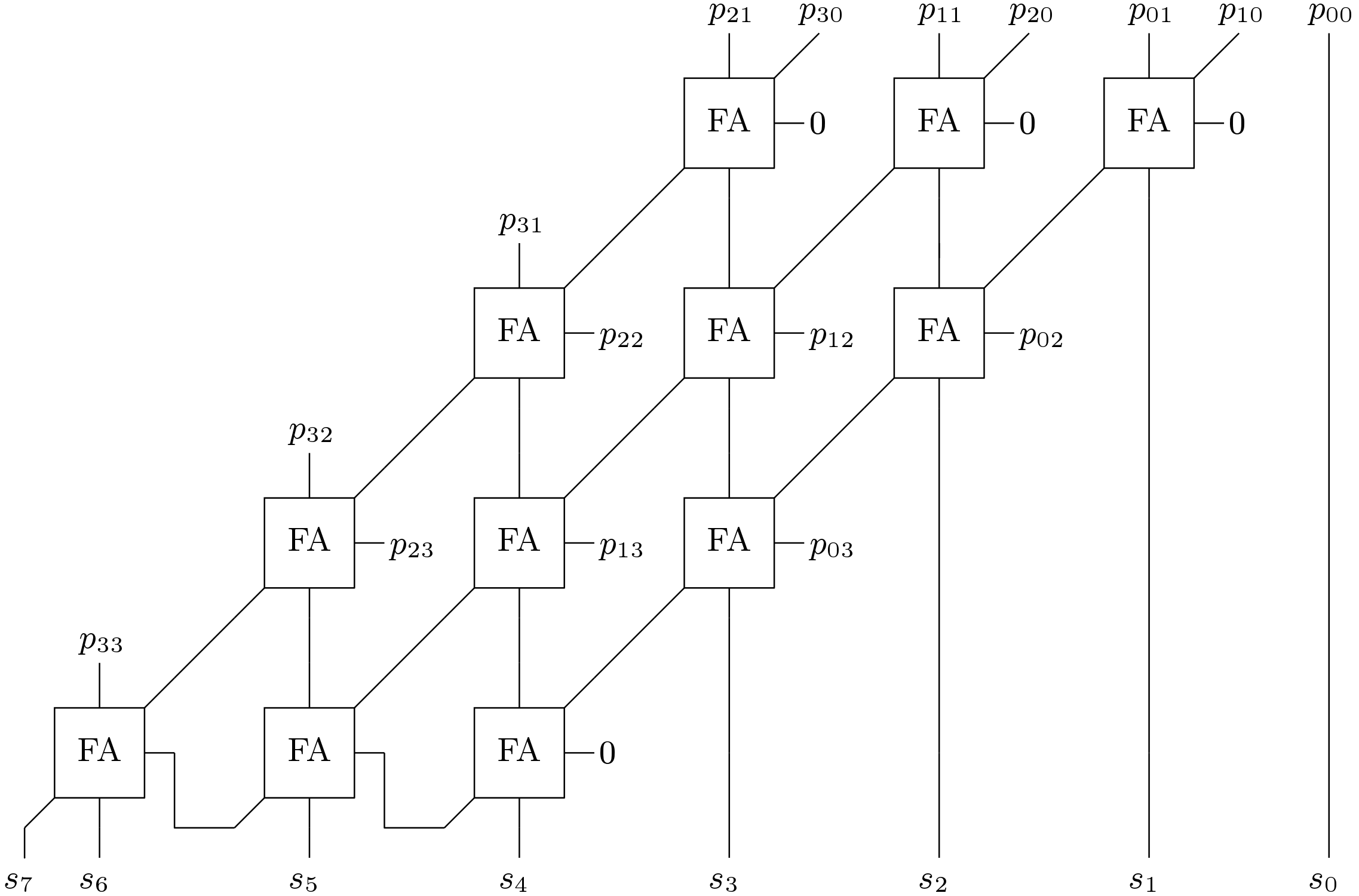
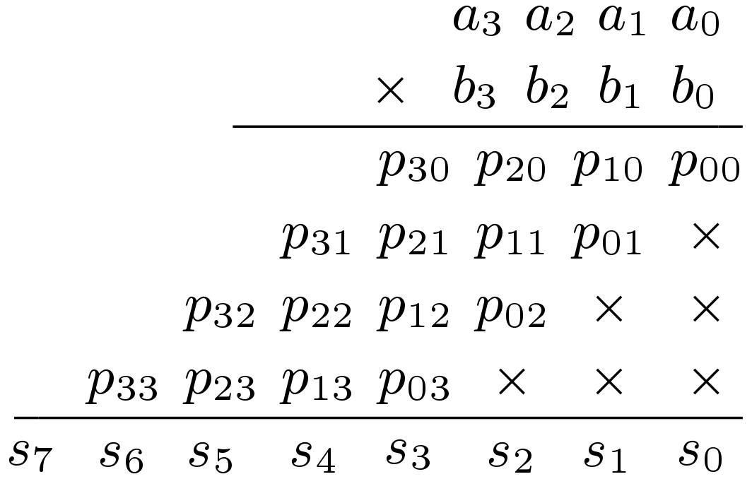
UNSIGNED ARRAY MULTIPLIER
An array multiplier is a digital combinational circuit used for multiplying two binary numbers by employing an array of full adders and half adders.
This array is used for the nearly simultaneous addition of the various product terms involved.
To form the various product terms, an array of AND gates is used before the Adder array.
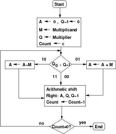
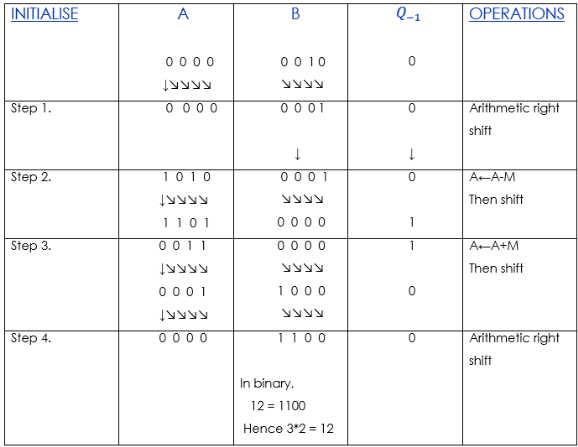
BOOTH MULTIPLIER
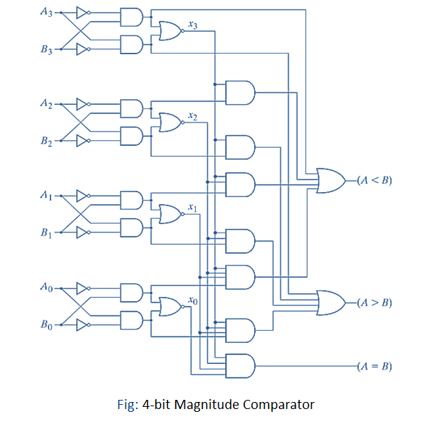
4 BIT MAGNITUDE COMPARATOR
A magnitude digital Comparator is a combinational circuit that compares two digital or binary numbers in order to find out whether one binary number is equal, less than, or greater than the other binary number.
We logically design a circuit for which we will have two inputs one for A and the other for B and have three output terminals, one for A > B condition, one for A = B condition, and one for A < B condition.
The circuit works by comparing the bits of the two numbers starting from the most significant bit (MSB) and moving toward the least significant bit (LSB).
At each bit position, the two corresponding bits of the numbers are compared. If the bit in the first number is greater than the corresponding bit in the second number, the A>B output is set to 1, and the circuit immediately determines that the first number is greater than the second.
Similarly, if the bit in the second number is greater than the corresponding bit in the first number, the A
If the two corresponding bits are equal, the circuit moves to the next bit position and compares the next pair of bits. This process continues until all the bits have been compared. If at any point in the comparison, the circuit determines that the first number is greater or less than the second number, the comparison is terminated, and the appropriate output is generated.
If all the bits are equal, the circuit generates an A=B output, indicating that the two numbers are equal.